Earlier this summer, I was training one of our new distributors from Central America and we started discussing Fixturlasers since they were a former reseller of those lasers. I was asking them how their system works and what they did for demos. I was pretty amazed to find Fixturlaser’s “rules for demos”:
- Don’t set the XA laser heads closer than 200 mm or else you will get bad repeatability.
- The XA system is very sensitive to backlash, so when turning the shaft, use both hands so you don’t create backslash errors. Whatever you do, don’t touch the brackets!
- Also don’t align the horizontal axis of the motor during the demo because it was very sensitive to the fixture movements (I think this is due to the “over under” technology).
- For uncoupled alignments, tell the customer clock measurement is better than Uncoupled Swipe™ or Pruftechnik’s Pass Mode™ because the Fixturlaser unit uses inclinometers rather than a swipe mode (this is just not true! – more on this in a future post).
- If possible just run the demo video.

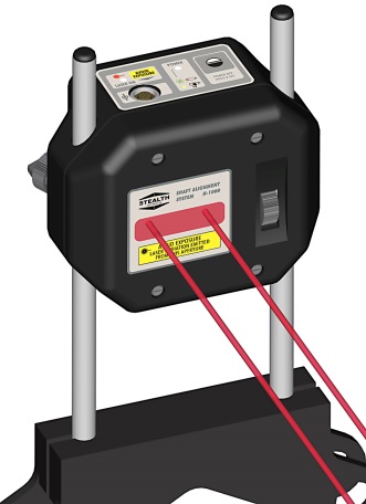
X-880 Dual-Beam™ Laser
Needless to say, we NEVER tell these things to our distributors, but this got me to thinking about why backlash is such a problem for these other systems when it is not really much of an issue for the X Series™ systems!
To do this, I will need to explain how we take data versus how Fixturlaser (Easy Laser and Gloi, too) does and talk a little math. Don’t be afraid, it won’t hurt too much! I will then show how the X-880 stacks up on one of our demo rigs that has a very sloppy coupling.
Dual-Beam™ Technology vs. “Over-Under” Technology
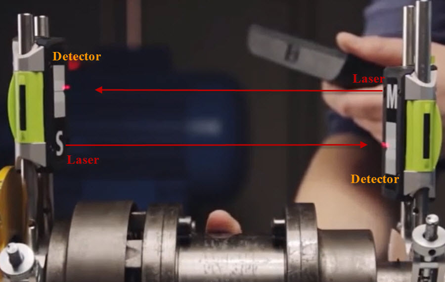
With our Dual-Beam™ Technology (X-770 and X-880), we have 2 laser beams, shooting side-by-side, in the same direction (we call this unidirectional), with 1 beam measuring the offset and the 2nd beam measuring the angle/gap by using an angular lens. We designed our technology this way because we know from our experience with high-accuracy, geo spindle-alignment applications, that you never want to have a laser beam on the moveable unit. If you do, then this will magnify repeatability errors and will cause the move screen to be very sensitive to motor movements, particularly for the V and H offsets.
Fixturlaser “Over Under” Technology
Now with Fixturlaser’s “over-under” technology, they have 1 laser/detector unit mounted on the driven unit, shooting toward motor, and a 2nd laser/detector unit mounted on the moveable unit, shooting back (under) toward the driven unit, so this means they have a laser mounted on the moveable unit. In my opinion, this precisely why Fixturlaser told the distributor above the “rules for demos” because they know this will make the demos more difficult!
Why did they design their technology this way? I’m not entirely sure, but my guess is that the “over-under” technology is very similar to the double-dial indicator method, popular at the time, and it was a simple technology to design and manufacture, plus they didn’t have our experience with spindle alignments!
How Does Backlash Affect Data Taking with Lasers?
Alright, now let’s talk about how Dual-Beam™ technology records alignment data. To record data, we record the V Offset and V Angle values at a minimum of 3 and up to 1,000 “clock locations” (points), depending on which data-recording mode we use, and because we use unidirectional “dot” lasers, backlash does not affect the measurements very much. Ok, but how much does slop affect our measurements?
Here is the formula to calculate the backlash error in the measurement: Error in V offset (or V angle) = radius- (cos (change in angle)* radius).
Let’s do an example to illustrate. First we need to find out the amount of coupling slop (which is the change in angle) and with our X-880 this is really easy since we can use the H Offset from our 4-axis head to measure how much the heads move relative to each other in inches and then we convert this to an angle. Now, in one of our demo fixtures, I measured the H offset change and determined we have .090” (3.5 mm) of slop in the coupling! With a 6-inch radius (center of the shaft to the target center line), this gives us about a 1-degree arc of coupling slop. Using the formula above, this give us the following error in the V offset value:
Error V offset = 6- (cos (1) * 6) = .0009” of error. So if one shaft rotates relative to the other by .090″, then the error in the data point at that location is .0009″.
Now I am not sure how Fixturlaser calculates their data, but I think that to determine the offset value they average the reading from laser/detector unit #1 from the reading from laser/detector unit #2. To get angle, they subtract the reading from unit #1 from unit #2 and divide by the distance between them. So how does backlash affect this technology? I don’t know for sure but we have a pretty good clue by looking at the Controlling Backlash video I found on Fixturlaser’s YouTube channel. Looking at the video, I estimate that the coupling has a similar amount of slop as our demo-rig coupling yet the the error in the measurement is up to .006″!
Sloppy Coupling Showing Amount of Indicator Error by Rotating the Shafts
So I think we can reasonable assume that the Fixturlaser have a similar error (maybe less?) in their measurements and if so, this explains why they created their “demo rules”! With a lot of the alignment tolerances being well below .005”, it’s not a surprise that the Fixturlaser video recommended using time-consuming techniques to control the backlash. What a pain!
One last thing: To compound the problem with Fixturlaser, Easy Laser and Gloi and sloppy couplings, these systems only offer 3 points of measurement data, so it is nearly impossible to smooth out any of these errors by taking lots of data points and allowing math algorithms to smooth out the fluctuations. However, with Auto Sweep™, where you can take 100’s of points in a sweep, along with a special curve-fitting algorithm to calculate the alignment data, even our smaller backlash error can be smoothed out very easily. This is why Auto Sweep™ is so repeatable!
X Series™ X-880 Repeatability with Sloppy Coupling
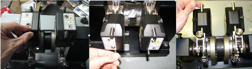
Ok, enough of the “tech” talk. How does the X-880’s repeatability stack up with such a sloppy coupling? Well I did a repeatability test on my demo rig by using Auto Sweep™ and probably the worst technique possible: using only the laser post to rotate the shafts. Furthermore, I rotated the shafts from 12:00 to 3:00 to 9:00 and back to 12:00. Both of these are big no-no’s, from what I’m told, because with a sloppy coupling, they maximize the measurement error. Also notice, I have the heads about 65 mm apart! I can even have them touching and it won’t affect the measurement at all!
X-880 Taking Data With Sloppy Coupling from 12:00 to 3:00 to 9:00 back to 12:00
Well how did the X-880 fare in this pretty difficult situation? See for yourself.
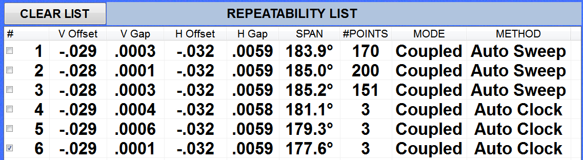
Couple6 Repeatability Table Showing Data Taken on Sloppy Coupling
The first 3 measurements (1, 2 & 3) were done using Auto Sweep™ rotating from 12:00 to 3:00 over to 9:00 and back to 12:00. Not bad, eh?
I then decided to test out our standard data-taking method, called Auto Clock™, where I took 3 only points of data (you can take up to 8!) at 3:00, 9:00 and 12:00. As you can see from second set of 3 measurements (4, 5 & 6), the data did not repeat as well as Auto Sweep™ but it is still pretty good and way better than .006″!
So what’s the take-away? Well, if you use “over-under” technology, you really do have to control coupling backlash as Fixturlaser recommends, but if you use our Dual-Beam™ technology you can take coupling backlash off your list of things to worry about! Just another way the X Series™ lasers help to make your life easier!