Analyze and correct machine tool geometry errors – flatness, straightness, squareness and parallelism
Hamar Laser’s Machine Tool Geometry Software is designed for machining center alignment. The program is used with our continuously rotating laser systems to measure and analyze the lines of motion of a machine’s main axes. Geometric errors, such as flatness, squareness, straightness and parallelism, are automatically downloaded through a computer interface.
Program features include:
- Records and analyzes misalignment data forup to 4 axes using one program
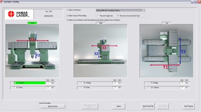
Analyzes flatness, straightness, squareness and parallelism line-of-motion geometry errors for up to 4 main machine axes. The software provides a top view, side view and front view for more efficient data taking. - Selectable setup by machine type from a pre-defined list of machines
The user can select from 5 different machine types and the software will automatically display a graphic of the selected machine. For additional flexibility, the user can add Autocad®-generated artwork and can customize axis labels (W, X, Y, Z, etc.) for individual machine types. - Real-time graphs show data as it is recorded for each line of motion
When taking data, real-time graphs automatically update with each newly-recorded point for instant identification of outliers (bad points). - Alignment graphs simultaneously show up to 4 lines of motion
Graphs show TIR, high and low points, tolerance bands, squareness and parallelism errors in inches or millimeters. The user can zoom in on straightness, squareness and parallelism graphs, choose one line of motion as the datum, and choose between “forward” and “backward” lines of motion. - Save, print and analyze recorded data
The user can save and print recorded data, as well as recall previously saved machine data for comparison to existing alignment conditions. Reports print the analysis graphs as well as all backup data. - User-definable tolerances
The user can define the straightness tolerance for an individual line of motion and for squareness and parallelism between axes. - Manual data entry
The user can enter data from field notes into the software for professional report generation, analysis and data storage.