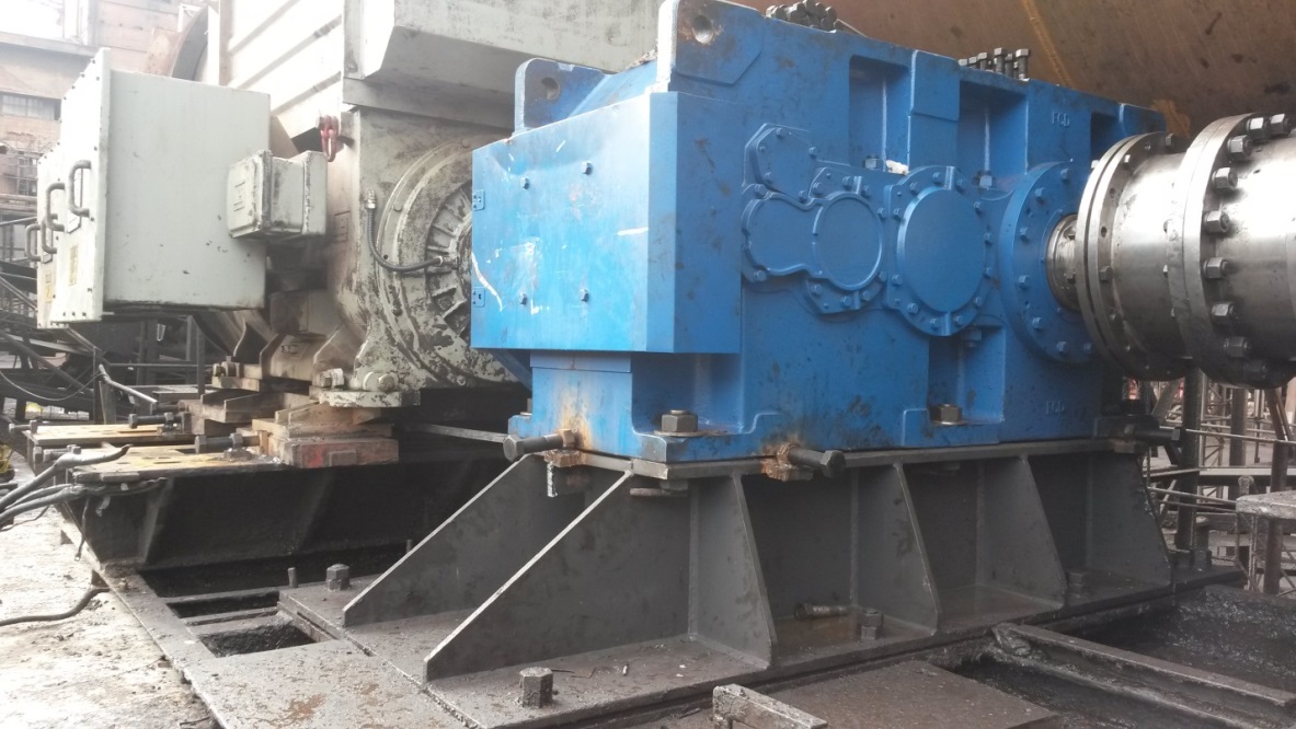

Came across this application from our distributor in Costa Rica. Here is a large gearbox where the shafts are hard to stop rotating. Due to this problem, the customer wanted to do the alignment without rotating the shafts, but we suggested they can rotate the shafts by using the X-880 and Auto Sweep™ instead!
How does this work?
Well with Auto Sweep™, you can take data at any clock location and stop at any clock location, so all you need to do is start rotating the shafts and let Couple6 (C6) take multiple rotations of data. Since C6 allows up to 1,000 points of data, you can let the shaft rotate as much as you want and it will keep recording data. This is actually an excellent way to get REALLY accurate alignment data because with all that data, any variability in it, maybe due to run out or to vibration, will tend to average out.
Here is a quick video to illustrate how C6 and Auto Sweep™ would handle this:
As the video shows, with Auto Sweep™ you can stop the shafts at any clock location, so this allows you to let the shafts stop wherever they want and C6 will automatically calculate the alignment results.
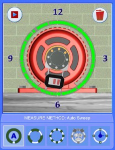
Step 4 Auto Sweep™ Showing the Shaft Stopped at 6:00
Another cool thing about C6 is when you go to the Step 5 Move Screen it will “rectify” the alignment results to correct for the shafts not being at 12, 3, 6, or 9, so you don’t have to try to stop the shafts at a clock location!
Also, with our Duo-Plane™ Live Move screen, you can also see BOTH the V and H alignment planes at the same time. So there is no need to rotate the shafts during the move like you do with the X-660 or X-670. That will really help on a monster machine like this!
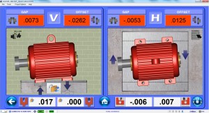
Couple6 Duo-Plane™ Live Move Screen
Here is the procedure for big machines like this:
1. Do the normal setup process.
2. Go to Step 4 and click on Auto Sweep™ icon and then the Record button ,which turns on Auto Sweep.
3. Then rotate the shafts and let them go until they stop. You can do multiple shaft rotations and Couple6 will continue to record the data and then average all the data (1000’s of points!) together into 1 set of rotation data.
4. When it stops rotating (can be anywhere), click on Stop and C6 will calculate the alignment results.
5. Repeat these steps to confirm repeatability. It should be very good!
6. You can then choose a set of data and then go to Step 5 to add the shim and do the moves. To enable the Duo-Plane™ Live Move Screen, you just need to leave the laser target at +/- 10 degrees from 12, 3, 6 or 9. Outside of those locations, C6 will still allow you to go the move screen but in Single Axis Mode. The great thing is no matter what clock location you leave the shafts, C6 will automatically “correct” the misalignment values so that it appears as if the target is at 12:00.
7. Now add the shim and then do the H axis alignment, again without rotating the shafts. You can then tighten down the bolts and still see the H alignment plane values (H off + H angle). This is very important since on the big machines it is quite possible that tightening the bolts will cause a small but significant movement in the H offset value. If this happens, you can loosen the bolt and “misalign” the H offset to compensate for this and then when you tighten the bolt, the H offset will come into tolerance. This will save a lot of time and help you to only have to do 1 alignment!
8. Hit the ReMeas button and verify the alignment by taking another set of data.
One big issue to note‼! – Notice we have rigidly mounted couplings here. It is important to loosen up the bolts on the couplings to allow the shafts to move. If you don’t 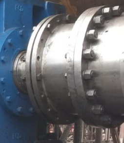 do this and there is a big misalignment, then the shafts will bend and not give good alignment data. There is a company that makes a tool for situations like this, it’s called Hutter Enterprises. The tool is called a Hutter Pin, which is used mainly in the steam turbine industry. These pins are used in place of the bolts on the rigid turbine couplings to “couple” the shafts together but allow radial movement of the shafts as they rotate. I suggest buying some of these for alignments similar to this one.
I’ll do another post soon about using our A-980NRA Non-Rotating Shaft brackets in shafts that can’t rotate. By for now!